Parts, costs, wiring diagrams, and fabrication files for inspecting the build and adapting it to your own hardware.
The parts list and build references are collected below. These resources are not yet a complete step-by-step build guide.
Parts & costs
The Excel workbook lists the parts, their functions, product links, prices, and build notes. It is organized by Transmitter, Receiver, and Ethernet systems, followed by irrigation parts, shared enclosures and accessories, and additional circuitry-building tools.
Entered prices are in USD and were verified by Casey Kenan on September 12, 2026. Prices may change. Blank costs are not included in the subtotals; additional tools are totaled separately from project parts. Check the listed specifications and build notes before ordering.
Board wiring
Transmitter ESP32 · Power & soil-sensor connections
The diagram shows the recommended USB-A–to–Micro-USB cable connection from the power bank to the Transmitter ESP32. My actual build used the alternative VIN/GND connection described below. Both soil sensors use 3.3 V and ground, with their analog outputs connected to GPIO32 and GPIO33 for separate readings.
Transmitter ESP32 power, shared sensor rails, and separate GPIO32/GPIO33 signal connections, with setup notes. Open full-size diagram ↗
This diagram follows the pictured 30-pin ESP32 board. Confirm your own board’s printed pin labels before wiring. Dots mark connected junctions; crossings with a white gap are not connected.
How I powered the actual build: I did not have the correct USB-A–to–Micro-USB cable, so I cut the available USB cable to access its power and ground conductors. I connected the power bank’s 5 V supply to the ESP32 board’s VIN pin and its ground conductor to GND, rather than using the Micro-USB port shown in the diagram.
For a new build, use the correct USB-A–to–Micro-USB cable instead of cutting one. Both methods can power a compatible development board, but confirm your specific board’s VIN input requirements and polarity first. The 5 V supply is not connected to the 3V3 or GPIO pins. Do not power through USB and VIN simultaneously unless your board’s documentation explicitly permits it.
Receiver ESP32 · MOSFET & solenoid wiring
The Receiver ESP32 supplies the control signal; the separate 12 V DC adapter supplies power for the solenoid through the XY MOSFET driver. This detail shows the signal, ground, power-input, and load connections.
Receiver ESP32 digital on/off control, USB power, and the separate 12 V solenoid power path, with setup notes. Open full-size wiring diagram ↗
Ethernet ESP32 · W5500 connections
The Ethernet ESP32 connects to the W5500 over SPI: GPIO13 for CS, GPIO27 for MOSI, GPIO19 for MISO, and GPIO14 for SCLK. The diagram includes 3.3 V power, shared ground, and a pin-by-pin guide to the pictured module.
Ethernet ESP32 and W5500 wiring, with each module pin explained and notes on time and email monitoring. Open full-size wiring diagram ↗
Pin functions were checked against the WIZnet W5500 datasheet; physical pad positions follow the supplied module photograph, and GPIO assignments follow the archived Ethernet firmware. Confirm your module’s labels, reset circuitry, and the ESP32 regulator’s available current before wiring.
Hardware & fabrication
Reusing PETG covers as perfboard bases
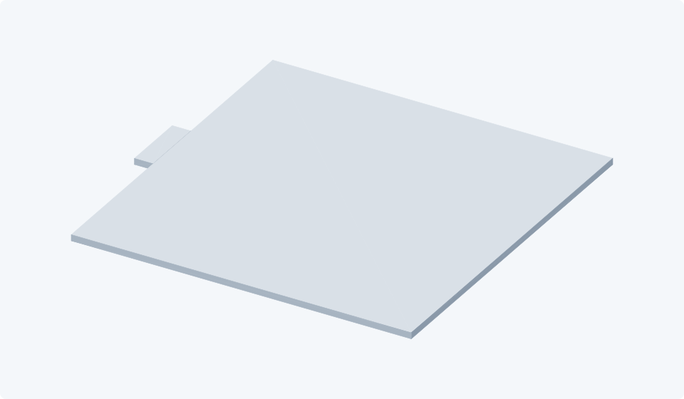
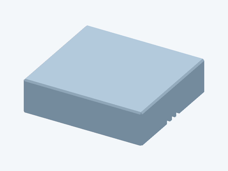
I repurposed the box covers printed from the STL files as bases beneath the soldered perfboards. I chose PETG for its high electrical resistivity, providing an insulating support for the solder joints and component leads protruding from the underside of each board. This helps separate those exposed connections from conductive mounting surfaces, reducing the risk of unintended current paths and short circuits.
Reliable circuit operation still depends on sound solder joints, adequate clearances, and verified connections; an insulating base alone does not guarantee zero signal loss.
Flat cover repurposed as a PETG base beneath the perfboard. Model preview rendered from my sliding-lid STL, not a photograph of the printed part.
Check soldered connections with a multimeter
After soldering and before powering the board, use a digital multimeter in continuity mode to check that points intended to be connected have an electrical path between them. Also check for accidental solder bridges between nearby pads that should remain separate.
Disconnect all power first—including the battery pack, USB cables, and 12 V supply—and follow the equipment’s instructions for safely discharging capacitors. Never use continuity mode on a powered circuit. A beep indicates a low-resistance path, not a guarantee of a good solder joint; other components can also provide a path, so compare the result with the wiring diagram and inspect the joint visually.
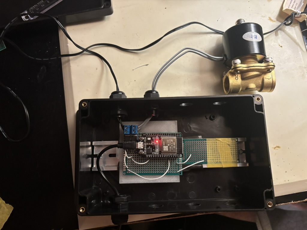
The outdoor assembly brought together hand-wired, soldered perfboards, sensor covers, mounting supports, protective enclosures, and the valve hardware. The photo below shows the Receiver inside its open enclosure. Board wiring contains the pin mappings and power connections; 3D-printed parts contains the cases, supports, and compartmented organizer files.
Receiver ESP32: board and control wiring inside the open waterproof protective enclosure, with the connected solenoid valve above it.
3D-printed parts
Custom storage and mounting parts, alongside two community-designed protective cases. Download the files to use in your own build; check component dimensions and print settings first.
My designs
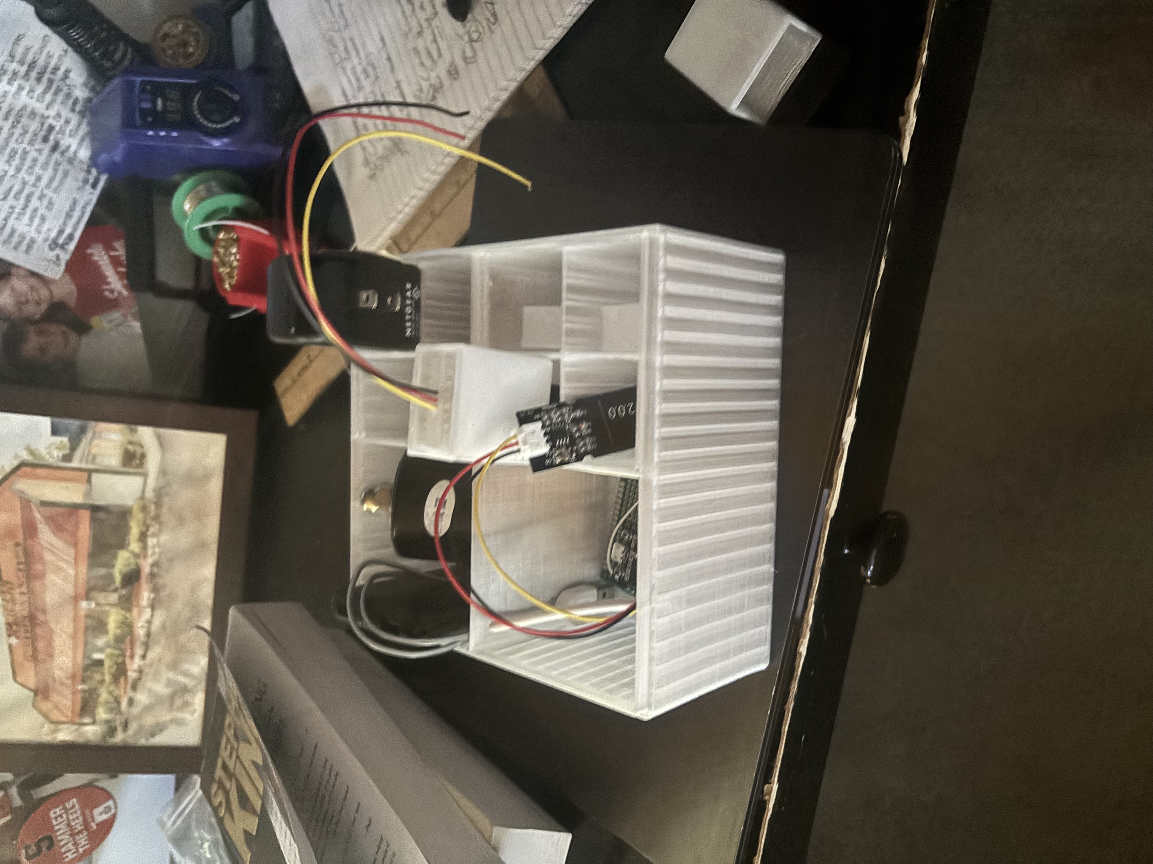
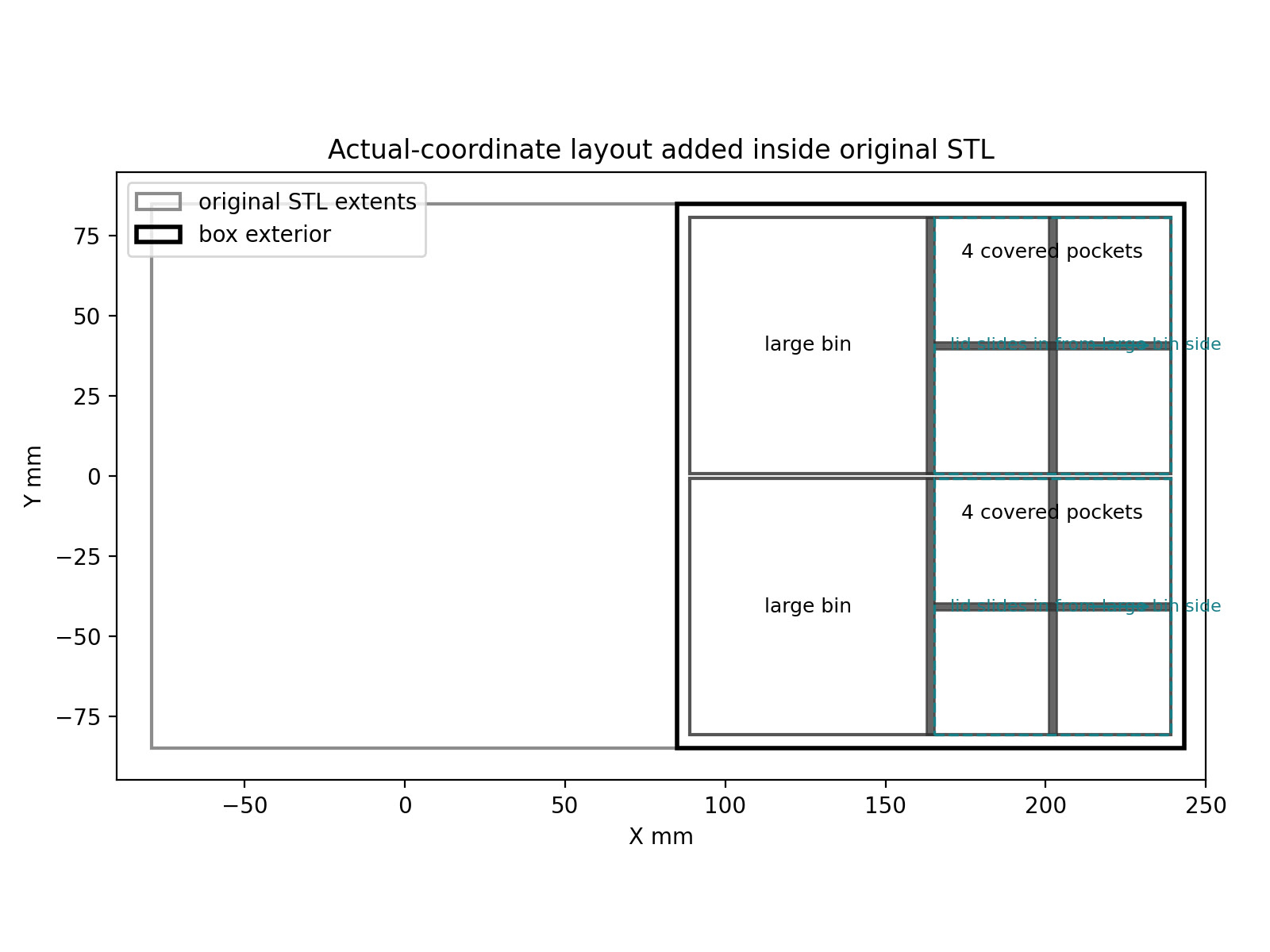
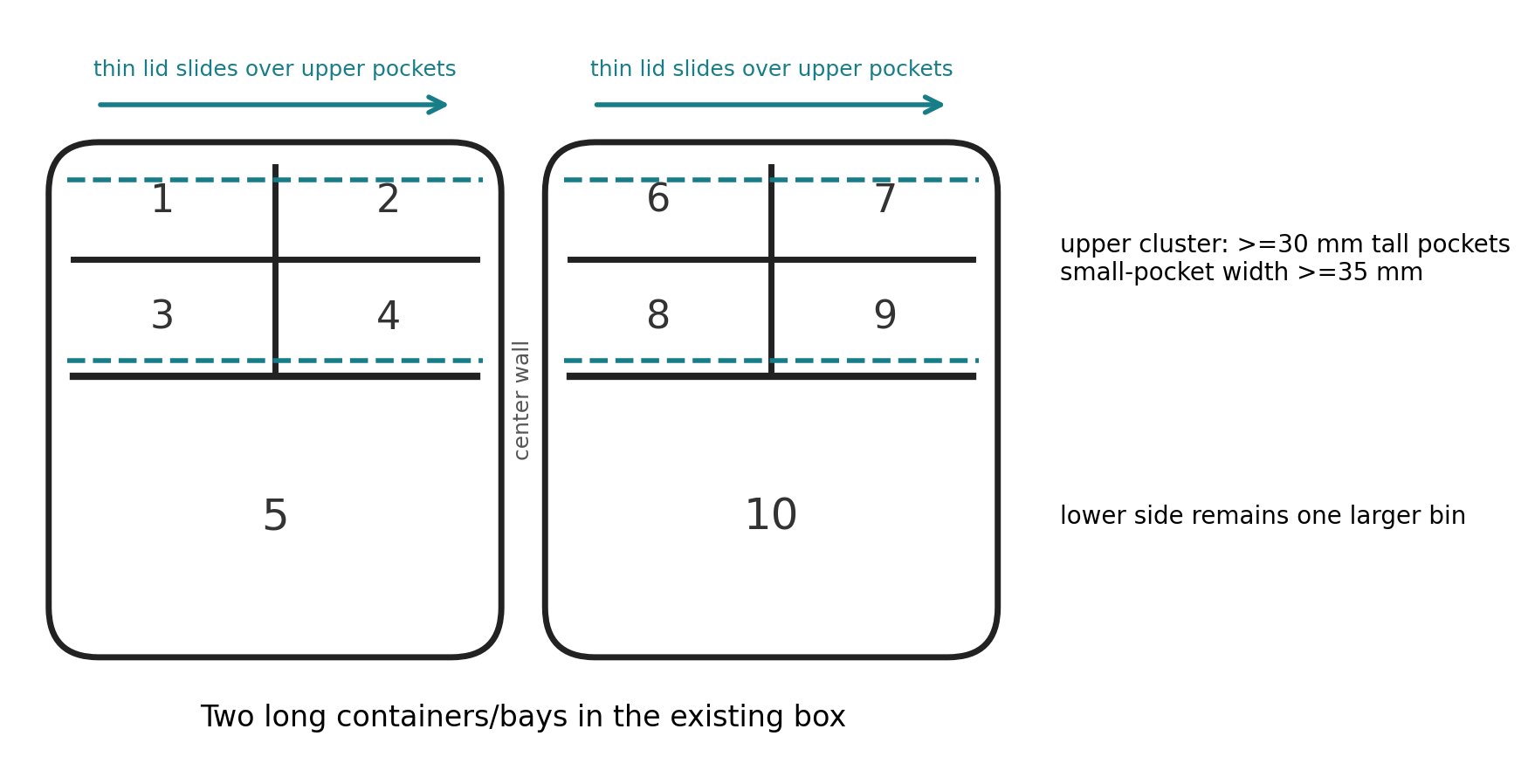
Plant Box — winter parts organizer
Designed by Casey Kenan
A compartmented container for keeping the irrigation parts together during winter storage, with separate spaces and sliding-lid pieces.
5 STL files: combined model, separate body, and lid pieces.
Ethernet raised perfboard support
Designed by Casey Kenan
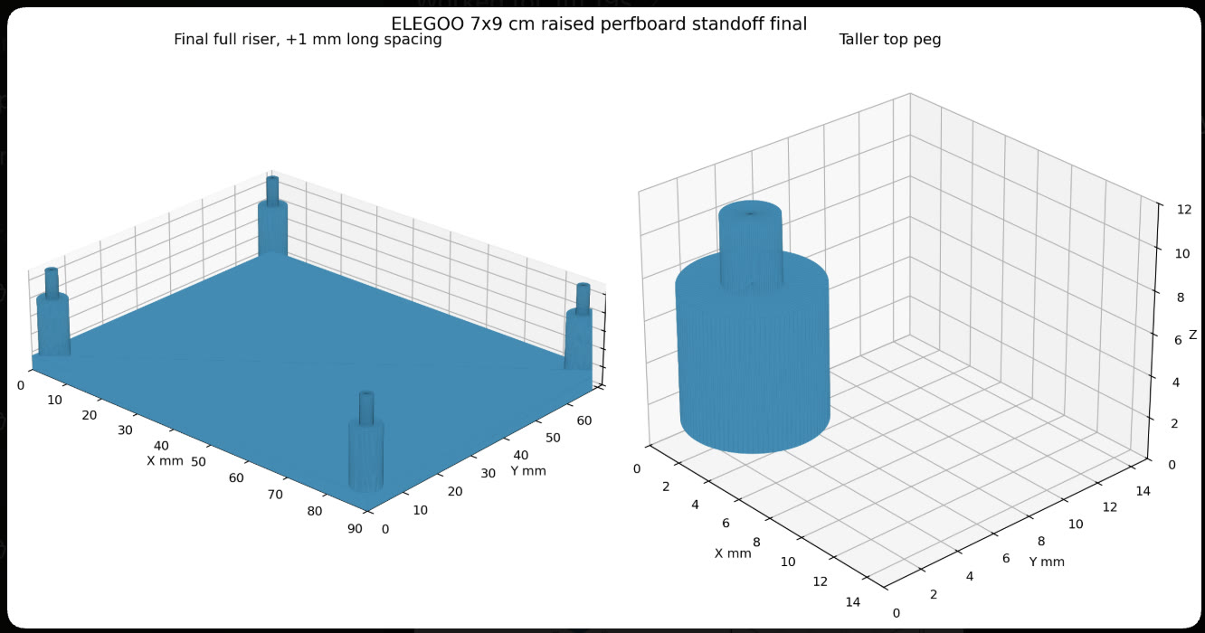
A raised support designed for a 7 × 9 cm (70 × 90 mm) perfboard in the Ethernet ESP32 assembly, as specified in the design preview. The mounting pegs are positioned to fit that board.
7 STL files, a bottom-case 3MF project, original model notes, and attribution. Follow the creator’s flexible-filament guidance for the lid parts.
Printed cases do not by themselves establish waterproof protection. Check fit and sealing for your installation. These downloads contain printed parts, not a complete irrigation build kit.
Software & code
Arduino IDE 2.3.10
I used Arduino IDE 2.3.10 to write, compile, and upload the C++ firmware to the ESP32 boards.
For the exact version used here, open the release page’s Assets section and choose the download for your operating system.
Project code
This overview draws on the firmware, test notes, and build files. Firmware source is not linked publicly here; printable parts are available in the 3D-printed parts section.